
Intro
After completing the robotic arm project, I began a new mechatronic assignment that gave us more autonomy regarding our design compared to my previous one. Although this project's timeline was very straightforward on paper (3D-Print->Assembly->Programming), this project introduced new challenges and concepts never seen before. Including the introduction to 360-degree continuous rotation servos, while these were only a half step up from 180-degree servos, they primarily introduced new programming and mechanical issues in this robot.
Fabrication
|
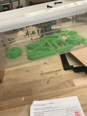
The first step of this project was to 3D print our design. To do this, I used 3D printing technology, which takes a 3D file and fabricates it with a plastic filament.
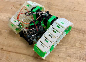
AssemblyThe next step, once all pieces were printed, was to assemble them. With this assembly, I installed two continuous rotation servos to allow the robot to roll. The primary problem that I faced during this time was the track-sprocket relationship of the robot. Specifically, the rotating sprockets were not gripping the holes of the 3D printed tracks. To solve this problem, the front and back bumpers were spaced out about .8 inches to allow more tension in the tracks, therefore, allowing the sprocket to grip the chain properly. Once I solved this problem, all that was left was the robot's programming for a charted course.
|
  |


Wiring and Programming
|
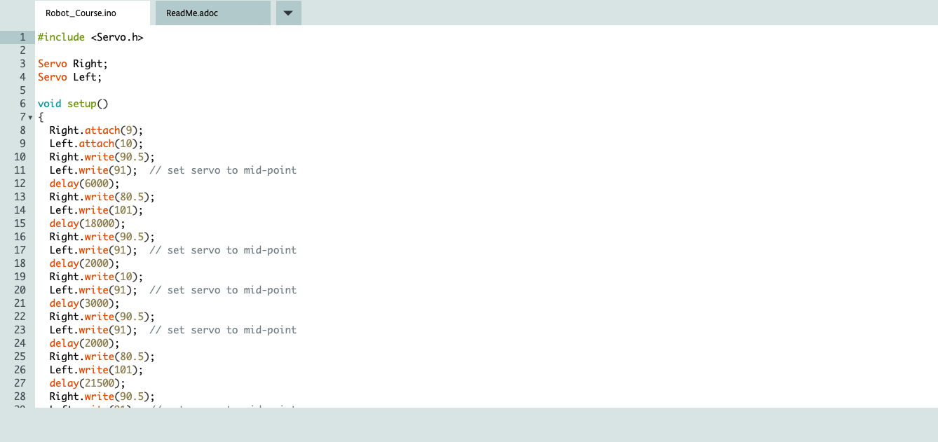
To begin wiring, I used an Arduino microcontroller which controlled both servos. During the step, I learned all the code needed to go through the final course, including manipulating the servos' speed and velocity. Although the coding was relatively straightforward, this step required a considerate amount of evaluation and testing to achieve perfection in the code. Nevertheless, with an understanding of the technology that I used, I completed the course before the deadline.
|
|


